Archive for August, 2009

Regulator wiring

Monday, August 31st, 2009

I bought a crimper and 20 6-pin connectors tonight at Ace, along with a new fuse for the power steering pump.  It blew a 15 amp so I’m trying a 25 amp.  I’ll need to upgrade my wiring to a thicker guage if it’s pulling that much.

So I’ll remake the phone cable connections and flip the wires so that are all “TDBR” – tang down, blue right.

Just thought, I bought 20 because I have 13 batteries.  So I need 26.  Oh wait, I can reuse 13 of them because half of the terminals are correct.  Whew.  My wife thinks I go to Ace to often, plus they are out for now.

It Worked! Almost…

Monday, August 31st, 2009

I resolved the issues with the controller.  I wired the negative contactor to a switch installed in the dash.  Flipping that on connects the negative HV to the controller.  My Dc/DC is tied to the open side of the contactor as well, so it kicks in then as well.  That’s a nice benefit to the switch because I can power all my 12V accessories off the pack with the controller still off.

Turning the key to run signals the controller to precharge and then close the postive contactor.  We hooked it all up and it worked.  Everything was wired except the open side of the contactor to the controller because I don’t have the circuit breaker in place yet.  Lacking a manual disconnect, I’d have no way to shut down the controller if something were to go awry.  Tomorrow I’ll see about adding in the circuit breaker and making the full connection.  Then we could go for a test drive.  Oh, about the almost…

Everything powered up like it should, but when I wiggled the steering wheel the motor turning the power steering pulley stopped under the load.  Rats.  The tires are a little flat and the car was stationary so that’s the worst situation the motor would be in, but I don’t know that it will work with the car in motion.  I’m leaning towards a test run tomorrow anyway.  The most difficult part, if the power steering doesn’t work, would be getting it back in the garage.

We will see.

It didn’t work

Sunday, August 30th, 2009

Today we made the final connections and turned the key.  Nada.  We fiddled with it for a couple of hours and gave up, planning to call the manufacturer of the controller tomorrow for some verification of the wiring diagram.

Basically I turned the key and the contactors didn’t close.  They are controlled by the Raptor 1200 controller, which precharges the internal components prior to sending the command to the contactors to open, dumping a voltage spike across the capacitors.  It wasn’t sending that command.

We tested the contactors by applying voltage across the leads and they are both operational, good.

I realized tonight that I have two contactors – one positive and one negative.  This is for redundancy and provides two electronic means to shutoff the motor by simply turning the key.  What I realized tonight was that the controller must have a continuous connection to the negative lead of the main pack to precharge.  That means you can’t have the controller running both contactors.  I think if I power the negative contactor off the chassis and key on, then the controller will follow normal sequence and close the positive lead on it’s own.

Tomorrow I will sit at work and watch the clock, waiting to go home and try again.  Tick tock tick tock.

Hey Man, what’s that cord for?

Saturday, August 29th, 2009

Today:

  • All regulators installed and checked for voltage at jumpers
  • Throttle potbox installed, connected to pedal by existing cable
  • Control board reinstalled
  • Low voltage components tested at key on (power steering motor, blower fan, vacuum pump)
  • High voltage wiring complete to circuit breaker and contactors
  • Broke stud on negative contactor (whoops)
  • Installed PFC-30 charger
  • Made 220V to 110V adapter
  • Tested charger, all batteries show 13.2V at 10 amp draw
  • Tested regulators – seemed ok, but the yellow leds didn’t act as I expected.  Reviewing the manual to see what’s going on.

Tomorrow we hope to do a test run!  Need to wire the negative contactor, circuit breaker, and low voltage wiring to the controller.

Pictures

Sunday, August 23rd, 2009

I installed the battery regulators 90% tonight. I need a couple more phone cords to make the final connections. Also rerouted some wiring from the brake vacuum so I could mount my potbox closer to the throttle cable. Finding a good location with clearance and the right approach angle for the throttle is proving a bit difficult.

Pictures:

So what’s left?

Saturday, August 22nd, 2009

I’m happy because I’m to a point where I know everything that has to be done.  Hard to believe.  I can’t say that I won’t have to make at least one more trip to Ace to buy some bolts though.

So what is left before we press the go pedal and promptly blow a fuse (probably)?

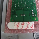
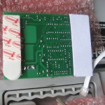
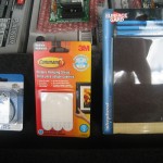
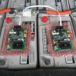
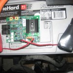
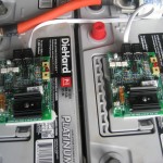
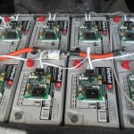
Next work session I’ll probably mount the battery regs.  I’m leaning towards a spacer and some adhesive to stick the regs right onto the batteries.  So that’s one trip to Ace for some number 6 screws and something rubber to screw into, like a half stopper.  Then I can put a piece of adhesive on it and glue it to the top of the battery.

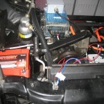
After that, I’ll mount the potbox, probably to the frame.  The control board has some flex in it (on purpose) so I don’t want the throttle to jump around if I hit a bump.

Next up would be wiring all the signal wires to the controller.  I think I have most of them already cut and terminated so it should be a matter of only connecting them.  I do need to make sure that I have fuses everywhere I need them.  I do not want to turn the key and blow up any number of parts that cost over a thousand bucks.

Before connecting all the high voltage batteries I’ll test the low voltage system.  Leaving off the lead to the Raptor I’ll be able to turn the key and the vacuum pump, motor blower and power steering motor should all run.  I’ll need to bleed the power steering system which will provide and opportunity to test the motor to see if it is strong enough.  I’ll raise the front wheels and turn from side to side with the motor running and see if it works while bubbling any air out of the lines.

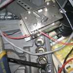
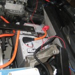
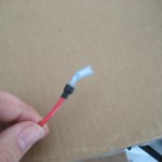
Also have to mount the battery charger.  It will go behind the driver’s seat and the Anderson 50 connector will drop below the floor to connect to the one I installed tonight.  I also need to have an electrician install an outlet for me  closer to the car and make an adapter to change from 220 to 110V.  I haven’t seen one anywhere so I think I need to make it.  I can only find NEMA 14-30R in a wall mount though so that’s not quite what I want.

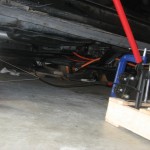
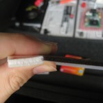
Finally, mount the circit breaker (emergency disconnect, with a lever within driver’s reach) under the car near the shifter.  This will require a waterproof box with openings for the negative 2/0 cable to enter and exit, as well as a way to run a lever out and into the car, probably to where the ashtray is.  So the response to smoke would be the same, to open the ashtray. Ha.

So maybe within the next two weeks this baby could roll on.  There is a car show in mid-September that it would be neat to get it to.  Hopefully that will work out.

Has anyone seen pictures?  Me neither.  Seems like I’m leaving out the pictures now that I have a bunch of stuff in.  I suppose you’ll have to forgive me, I’m spending my time getting it done instead of logging information about it.  I’ll catch up once I’m done.  But will it ever really be done?  Probably not.

Update on Progress

Saturday, August 22nd, 2009

So a few days ago I thought I was going to take a break from working and let things settle down after the whirlwind of making battery racks and mounting so many things.  The good news is I ended up not making it that long.  After a frustrating day on the computer at work (new software that doesn’t work and has to be used) I left early and decided to work a little on the car.  That was a Thursday and things clicked off pretty well.

So roll forward to last Saturday and I woke up early and went out to wash the gas-car.  I found that there were little specks all over it making it feel kind of gritty.  I hadn’t washed it in a few weeks so I attributed it to road grime but after closer inspection I found out it was metal dust from all the cutting and grinding on the Trans Am.  So learn a lesson from me and move your good cars further away while working on the ev convert.  Most of it came off with a clay bar but I’ll need to go over it another time or two to get the stubborn bits.  I needed my energy that day to get some car stuff done…

So last Saturday and some evenings this week I finished a bunch of small tasks and actually got a little ahead of myself on some things.  A list:

  • Completed high voltage wiring.  I have not connected all the batteries because I don’t want 156 volts humming around while I’m still doing the low voltage, but everything is ready to bolt in.
  • Completed and mounted the main control board.  High voltage wiring is complete and installed from fuse to contactor to shunt to controller and from the controller to the motor.
  • Installed the DC/DC controller and wired it in
  • Completed wiring for the motor blower
  • Completed wiring for the power steering motor
  • Made wires and a terminal block that will be electrically live with key on and tied all my relays into that.

So I said I got ahead of myself.  Today I removed the main control board after scrapping my hand up one too many times.  I thought I could install the battery regulators just reaching under it but it was a pain.  While I have it out I completed the 6 guage wire wires that will connect the charger to the most positive battery up front and most negative in the back.  I bought two lengths, 10-ft of black and 5-ft of white.  Thinking that I had wire to spare I cut off about 1.5-ft of the white to use to tie the DC-DC converter to the negative battery post.  That left me with about 2″ to spare when I ran the wires from the front to the back.  I had to reroute the long wire from one side of the car to the other because it was too short, but ultimately it worked out.  I have another tip to add to my collection for future convertors: While it is a good idea to do a test run of your wiring to make sure it is long enough, you shouldn’t get over zealous and actually attach the wire to the car, especially if you haven’t crimped the lugs on because you don’t know how long the wire needs to be.  I was able to remove only one clip and make my crimp on the side of the car, but it was close.

I also tested my pot box and it seems pretty linear.  I hope the fire didn’t damage it.  Oh, you didn’t know about the fire?  Well I’ll tell you.  I was going off memory and for some reason I thought you had to connect a battery to the pot box so the resistance could be measured.  I did that and connected the multi-meter to the wires that will connect to the Raptor.  Raptor is cooled to say than controller.  As soon as I moved the throttle lever, the battery dumped who knows how many amps into the too small wires that probably shouldn’t have been connected that was anyhow.  So the wires puffed and were on fire.   I blew it out and figured out that a resistor works whether there is a load going through it or not.  So I undid all the connections except for the multi-meters leads and it still shows me 0-5k ohms resistance, pretty linear but a little jumping.  It could have been my unsteady left hand holding the assembly and my unsteady right hand  moving the lever, so we’ll see how it goes once it it mounted to something solid.

Regulator Cables

Friday, August 21st, 2009

I had to edit this one because it was completely wrong.  I couldn’t find the manual for the regulators and the website had a bad link at the moment.  It is fixed now so I reread the manual and see what went I hadn’t noticed before.

I found 12″ 6-pin connectors at Walmart and compared the wiring and they were in the right order.  Problem was when I looked at them through the box the tangs were facing different directions.  According to Rudman, “TDBR” means tang down, blue right.  With the wires I purchased that is true for one but opposite for another.  That makes sense from the perspective of connection a phone to a socket, but not connecting in serial for communication.  I’ll cut off the plastic terminals on the wires I have and recrimp them with new 6-pin terminals.  More expensive than buying a spool of cable and terminals and doing it that way to begin with, but now I know store bought cables probably won’t work.

Trans Amped – The Poster

Tuesday, August 18th, 2009

So this is something I made soon after changing the name from EV Trans Am to Trans Amped.  It was actually a Valentine’s gift to my wife to show her how awesome her hubby is.

Taking a breather

Wednesday, August 12th, 2009

I’ve been taking some time off the project.  My primary time to work on it is in the evenings.  Our garage faces west so the sun sets and comes into it, making it pretty dang hot, not to mention bright.

I’m thinking about taking a few days off around Labor Day and trying to finish it in one big push.  We’ll see.

I need a couple more pieces (lugs that fit the shunt, covers for some battery regulators, regulator phone cords…) but the major stuff could be done now.  Still haven’t thought of a good way to mount the battery regulators though.