Posts Tagged ‘wiring’

Nothing to See Here

Friday, April 23rd, 2010

The past few days I’ve been working on the LV wiring. Mostly cleanup, re-routing wires. I spent about an hour today moving wires from one side of a box to the other so they could be routed into my new box. So in summary it’s progress but you wouldn’t know it to look.

Getting closer though.

Big Progress Day

Saturday, April 3rd, 2010

Got a lot done today, focusing on the rear of the car. The regulator octobox is cleaned up and I have the rest of the bolts and nuts needed for it. It is bolted to the car and ready for the regulators to be inserted.

The wooden battery cover was cut, routed and installed on hinges. I have a slight clearance issue with a battery post but I think I can work around that with shorter bolts on the hinge or rotating the battery if need be.

Last thing to do is route the AC from the gas cap to the charger and the DC from the charger to the battery pack Anderson connection. Once those are done the rear batteries can be reinstalled and wired up.

The front HV box will be ready to install after I mount the DC converter to its side. Then the Raptor can go back in followed by a cleanup of the LV wiring (vacuum pump primarily) and we’re ready for another road test.

I have an idea for the wooden cover.  I’d like to stain it somewhat dark then have the Trans Amped logo printed across it, possibly with some stats on the car as well.  I’ll probably focus on the logo to keep it clean.

This is the Trans Amped logo that my brother had made for my birthday.  The + and - are nicely incorporated into the traditional Firebird look.

This is the Trans Amped logo that my wife and brother had made for my birthday. The + and - are nicely incorporated into the traditional Firebird look.

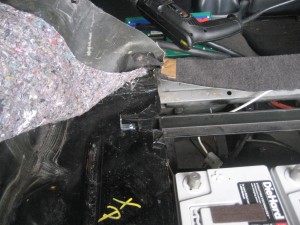
Drilling holes for the 'octobox'

Drilling holes for the

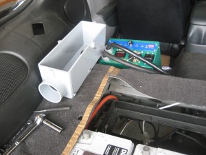
Mounted 'octobox' for the rear regulators

Mounted

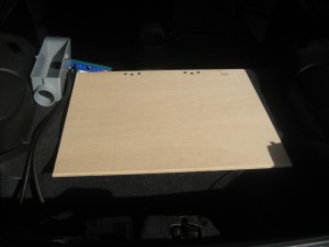
Wooden cover installed.

Wooden cover installed.

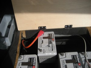
Conflict with hinge and battery post

Conflict with hinge and battery post

Battery Regulator Wiring

Tuesday, March 23rd, 2010

I worked a little more on the new wiring for the battery regulators.

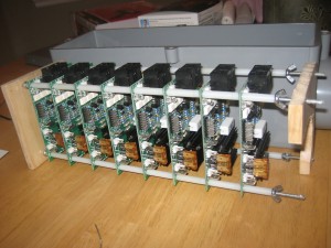
Here are the regulators mounted on the metal rods.  Behind is the junction box they fit in.

Here are the regulators mounted on the metal rods. Behind is the junction box they fit in.

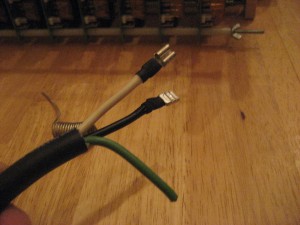
These are the wire ends that attach to the regulators.  I intended to strip out the green wire but it looks like the 3 wires are spiraled so it would be too difficult.  I couldn't find 12/2 with other than extension cord and I didn't like the look of that.

These are the wire ends that attach to the regulators. I intended to strip out the green wire but it looks like the 3 wires are spiraled so it would be too difficult. I couldn't find 12/2 with other than extension cord and I didn't like the look of that.

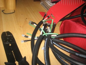
These are the 8 wires that connect to the rear regulator rack.  Crimped, soldered and wrapped.

These are the 8 wires that connect to the rear regulator rack. Crimped, soldered and wrapped.

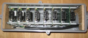
The rack inside the junction box with a wire running down the side.  All 8 will enter the box through the top.  I still need to add a bar on the right side to keep the wires from putting stress on the top regulator.  It will be a thin metal strip across the threaded rods.

The rack inside the junction box with a wire running down the side. All 8 will enter the box through the top. I still need to add a bar on the right side to keep the wires from putting stress on the top regulator. It will be a thin metal strip across the threaded rods.

This is the top where the 8 wires will exit the junction box and continue to the rear battery pack.

This is the top where the 8 wires will exit the junction box and continue to the rear battery pack.

Interior Cleanup

Saturday, October 10th, 2009

Today I upgraded the switch that turns on the negative contactor. It’s a bright red, lighted rocker switch that should be easy to remember to turn off. I also reinstalled the interior console and rerouted the emergency rip cord to come out by the driver’s right knee. I’ll attach a red handle or something to it soon.

Also cut off a couple bundles from the engine wiring harness. I think I only cut wires I don’t need. I don’t have most of the sensors anymore so I don’t see why I would need them, but they may go to something I wasn’t thinking about. I did that so I could easily run the plugs to the transmission. Now the speedometer should work, as well as the reverse lockout.

It Worked! Almost…

Monday, August 31st, 2009

I resolved the issues with the controller.  I wired the negative contactor to a switch installed in the dash.  Flipping that on connects the negative HV to the controller.  My Dc/DC is tied to the open side of the contactor as well, so it kicks in then as well.  That’s a nice benefit to the switch because I can power all my 12V accessories off the pack with the controller still off.

Turning the key to run signals the controller to precharge and then close the postive contactor.  We hooked it all up and it worked.  Everything was wired except the open side of the contactor to the controller because I don’t have the circuit breaker in place yet.  Lacking a manual disconnect, I’d have no way to shut down the controller if something were to go awry.  Tomorrow I’ll see about adding in the circuit breaker and making the full connection.  Then we could go for a test drive.  Oh, about the almost…

Everything powered up like it should, but when I wiggled the steering wheel the motor turning the power steering pulley stopped under the load.  Rats.  The tires are a little flat and the car was stationary so that’s the worst situation the motor would be in, but I don’t know that it will work with the car in motion.  I’m leaning towards a test run tomorrow anyway.  The most difficult part, if the power steering doesn’t work, would be getting it back in the garage.

We will see.

It didn’t work

Sunday, August 30th, 2009

Today we made the final connections and turned the key.  Nada.  We fiddled with it for a couple of hours and gave up, planning to call the manufacturer of the controller tomorrow for some verification of the wiring diagram.

Basically I turned the key and the contactors didn’t close.  They are controlled by the Raptor 1200 controller, which precharges the internal components prior to sending the command to the contactors to open, dumping a voltage spike across the capacitors.  It wasn’t sending that command.

We tested the contactors by applying voltage across the leads and they are both operational, good.

I realized tonight that I have two contactors – one positive and one negative.  This is for redundancy and provides two electronic means to shutoff the motor by simply turning the key.  What I realized tonight was that the controller must have a continuous connection to the negative lead of the main pack to precharge.  That means you can’t have the controller running both contactors.  I think if I power the negative contactor off the chassis and key on, then the controller will follow normal sequence and close the positive lead on it’s own.

Tomorrow I will sit at work and watch the clock, waiting to go home and try again.  Tick tock tick tock.

Update on Progress

Saturday, August 22nd, 2009

So a few days ago I thought I was going to take a break from working and let things settle down after the whirlwind of making battery racks and mounting so many things.  The good news is I ended up not making it that long.  After a frustrating day on the computer at work (new software that doesn’t work and has to be used) I left early and decided to work a little on the car.  That was a Thursday and things clicked off pretty well.

So roll forward to last Saturday and I woke up early and went out to wash the gas-car.  I found that there were little specks all over it making it feel kind of gritty.  I hadn’t washed it in a few weeks so I attributed it to road grime but after closer inspection I found out it was metal dust from all the cutting and grinding on the Trans Am.  So learn a lesson from me and move your good cars further away while working on the ev convert.  Most of it came off with a clay bar but I’ll need to go over it another time or two to get the stubborn bits.  I needed my energy that day to get some car stuff done…

So last Saturday and some evenings this week I finished a bunch of small tasks and actually got a little ahead of myself on some things.  A list:

  • Completed high voltage wiring.  I have not connected all the batteries because I don’t want 156 volts humming around while I’m still doing the low voltage, but everything is ready to bolt in.
  • Completed and mounted the main control board.  High voltage wiring is complete and installed from fuse to contactor to shunt to controller and from the controller to the motor.
  • Installed the DC/DC controller and wired it in
  • Completed wiring for the motor blower
  • Completed wiring for the power steering motor
  • Made wires and a terminal block that will be electrically live with key on and tied all my relays into that.

So I said I got ahead of myself.  Today I removed the main control board after scrapping my hand up one too many times.  I thought I could install the battery regulators just reaching under it but it was a pain.  While I have it out I completed the 6 guage wire wires that will connect the charger to the most positive battery up front and most negative in the back.  I bought two lengths, 10-ft of black and 5-ft of white.  Thinking that I had wire to spare I cut off about 1.5-ft of the white to use to tie the DC-DC converter to the negative battery post.  That left me with about 2″ to spare when I ran the wires from the front to the back.  I had to reroute the long wire from one side of the car to the other because it was too short, but ultimately it worked out.  I have another tip to add to my collection for future convertors: While it is a good idea to do a test run of your wiring to make sure it is long enough, you shouldn’t get over zealous and actually attach the wire to the car, especially if you haven’t crimped the lugs on because you don’t know how long the wire needs to be.  I was able to remove only one clip and make my crimp on the side of the car, but it was close.

I also tested my pot box and it seems pretty linear.  I hope the fire didn’t damage it.  Oh, you didn’t know about the fire?  Well I’ll tell you.  I was going off memory and for some reason I thought you had to connect a battery to the pot box so the resistance could be measured.  I did that and connected the multi-meter to the wires that will connect to the Raptor.  Raptor is cooled to say than controller.  As soon as I moved the throttle lever, the battery dumped who knows how many amps into the too small wires that probably shouldn’t have been connected that was anyhow.  So the wires puffed and were on fire.   I blew it out and figured out that a resistor works whether there is a load going through it or not.  So I undid all the connections except for the multi-meters leads and it still shows me 0-5k ohms resistance, pretty linear but a little jumping.  It could have been my unsteady left hand holding the assembly and my unsteady right hand  moving the lever, so we’ll see how it goes once it it mounted to something solid.

Making more cables

Sunday, August 2nd, 2009

I made a couple more HV cables Friday night.  The bolts on the circuit breaker and shunt are bigger than the holes in the lugs.  I’d already run the cable to length for the CB so I drilled out the 5/16 hole to 3/8.  It took the tinning off the lug but it will be covered with heatshrink and the hole won’t actually be in contact with the washers so no worries.

I’m a little confused about the motor wiring.  The diagram from NetGain says it doesn’t matter which line from the controller goes where.  It seams that if a reversing contactor can be used to change the direction of the motor by switching wires (I’m not 100% on how reversing contactors work though) then the motor would spin the wrong way if wired wrong.

The other complicating point is that the preferred wiring configuration doesn’t match the wiring given in the bench test.  Given that the bench test worked how we wanted I’m wondering why we can’t wire it that way.

Also, the A1 to S1 connection on the WarP 11 is so close that two lugs won’t even fit between.  I either need a copper bar to drill out or make a long enough cable that can bend 180 degrees and not interfere with the A2 or S2 connections.

Getting close, counting down by weeks.

Continuing on

Wednesday, July 1st, 2009

A little more progress fitting the rear battery rack last night. We may be able to finish up tomorrow with the tray and then will need to make a cover that will open to access (and show off) the batteries.

With the front complete I can do all the wiring and find out if I’m missing anything. I think I’ll add another contactor so there is one on both the positive and negative leads of the battery pack. That provides redundancy in turning on and shutting down the power to the controller.

I also need to add a manual disconnect, preferably a circuit breaker that can be activated easily from the driver’s seat in the event of an overload from the batteries or runaway motor or any other expensive misfortune. I’ve only seen one that is commonly used and I’m not sure if it provides enough protection to not nuisance trip. We’ll, I’ve seen others but they cost a whole lot more. Right now I’m leaning towards using it anyway and replacing it with a beefier unit if it comes to that.

Remaining items:

  • Where is my charger and battery regulators?  I ordered them a little over a month ago.
  • Manual disconnect, second contactor, ammeter shunt and wiring layout
  • Complete battery cables
  • Complete low voltage wiring (PS motor, brake vacuum, which also needs to connect to the A/C vent, master on switch for HV system, etc.)

Is moving within a month under E-power reasonable?  As luck would have it work is going to be very busy so hopefully I’ll keep making progress.  Pictures are overdue, next week maybe.

Wiring idea

Monday, May 11th, 2009

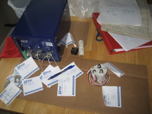
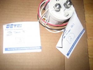
Instead of constantly thinking about the wiring song (The battery negative connects to the fuse wire, the fuse wire is connected to the funny bone, the funny bone is connected to the motor controller…) I decided I just needed to lay it out in a way that makes sense to me. Here is what I came up with – tags of paper tied to each part with a label and designation of where it goes. That way when I’m laying it out in the car I only have to think about connecting “1” to “1” and “2” to “2” instead of + and – and whatever.

I’ll use the string again once things are going in the car to determine how much cable I’ll need for that connection.