Motor Installation. This is a long post describing the details on installing the motor. I’ll clean it up later and create more of an informational page instead of a description of what happened. It’s partially written in both manners, so you’ll have to excuse that.
Thursday, March 5, 2009
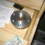
After bringing the boxes inside, I began opening them to see everything that had been ordered. The contents were:
1 – Hub adapter to mate the flywheel to the motor
2 – Spacer ring to properly locate the flywheel within the bellhousing
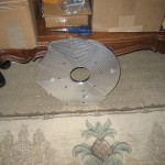
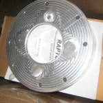
3 – Adapter plate to mount the motor to the bellhousing
4 – 35 feet of 2/0 flexible cable for battery wiring
5 – PB-6 potentiometer for throttle control
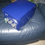
6 – DC Power Systems Raptor 1200 motor controller
Everything was accounted for so I started mentally assembling the pieces in my head. The hub adapter was too tight a fit to slide onto the motor drive end so I didn’t want to try fitting that until it was ready to stay on. While looking at it though, I had a moment of panic, noticing that the 6 bolt holes were not symmetric. Thinking this was a machining error, I trudged out to the garage to line it up with the flywheel and make sure it wouldn’t fit before calling the vendor.
Sure enough, the bolt holes didn’t line up, but was otherwise a good fit. The stock crank has a locator pin on it so the flywheel can only go one way. The hub adapter did not, so I was able to rotate the flywheel for 6 different mounting positions. Turns out, on possible position 5 of 6, all the holes lined up perfect. Just to be sure, I started a bolt a few turns into each of the holes and it worked!
The next anxious moment was while inspecting the adaptor plate. There are two locating pins on, one on each side, of the transmission bellhousing. There were holes in the adaptor plate for the pins so I thought I’d need to have those drilled out. Fortunately, my memory was the only thing backwards and the pins are on the adaptor plate (facing down at the time) and the holes are on the transmission. Whew.
The last thing was to locate the keyway for the hub adapter. I couldn’t find it in the boxes, but eventually thought to look in the bag that held the bolts for the motor adapter. It was there, thankfully, since I had only assumed it was included. I’ll work on putting together a checklist of items to consider when ordering from vendors.
With everything checked out, I made a list of all the parts I would need to complete the motor installation. One of the flywheel bolts was damaged during engine disassembly so I opted to replace them all with new ones from Napa. Also, the adapter and motor had 8 holes for mounting but only 4 bolts were included from the vendor. I’d feel better with 8 so I added those to the list.
Another item that was needed were new, longer bolts for the bellhousing to adapter plate connection. The bellhousing previously bolted directly to the engine block, but the adapter plate came with holes in those locations. I think that makes sense because the stock bolts would almost pass completely through the adapter plate were the holes threaded. 6 bolts about 2″ long would do the trick.
Miscellaneous items included some blue threadlocker and some temporary shorter bolts for connecting a chain to the motor for lifting.
I called my brother to see when he’d be able to help, so we set Saturday morning as the installation time.
Friday, March 6, 2009
Knowing I couldn’t install anything until Saturday, I set out Friday to make sure I had everything I would need to complete the installation. First, I hauled the WarP 11 out to the garage. For the past month or so, the motor has been sitting just inside the front door, where my brother and neighbor pulled it inside after unloading it from the truck. To help reduce the freight dock look and instead add to the decor (the red of the WarP matches a plant inside the door), I rolled the motor out of the box and off the crate onto my creeper. That would also make it somewhat mobile since now it’s on wheels, as Ithaca would sing.
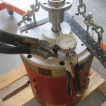
I rolled the motor out to the door from the laundry room to the garage and then slowly tipped it over the step. Even with the creeper making an easy handle, that sucker is still heavy. I setup the engine hoist and used it to lift the motor on end and set it down on the shipping pallet. This allowed the front shaft to extend below the support for the motor, between the wood slates. In this position, I was able to test the drive shaft for trueness using a dial indicator. My intent was also to test with the hub adapter on, and again with the flywheel bolted up. However, with the tight fit of the hub adapter, and the flush mount of the flywheel, there weren’t any adjustments I would be able to make to correct any minor inaccuracies. Since I couldn’t correct anything, I opted to just install it and we’ll see how it goes. If there are vibrations once installed I’ll trouble shoot it then.
Next up was a shopping trip to Napa Auto Parts and Ace Hardware. At Napa, I got the flywheel bolts and some hose and adapter I’ll need for the vacuum pump I’ll install later. At Ace, I picked up the rest of the bolts, washers, nuts, and threadlocker from the list. They didn’t have 6 of the same bolts I would need for the bellhousing, so I got 4 of one type and two of the others. They’re a bit longer than I wanted also, so I’ll probably replace them later with a better choice.
Saturday, March 7, 2009
The Big Day!
I started with some layout of everything we would be using and general cleanup of the garage. One of the biggest helps I’ve noticed is having a clean work area, so I was hoping to keep everything where we’d be able to find it.
While doing so, I arranged all the bolts together by application and noticed that the washers I bought at Ace, while 3/8″ inner diameter, where a larger outer diameter and would not fit within the recesses of the adapter plate. So our first task was to either drill out smaller washers to accept the 3/8″ bolts, grind down the larger washers diameter or cut off a few threads of the bolts. We cut down the bolts because the washers are only used to adjust the length of the bolt entering the motor. A trick for doing so is to wind a nut onto the bolt past the point of cutting, cut the bolt with a hacksaw or dremel, then remove the nut. Using this method ensures that you can remove the nut and that normally straightens out any threads that were damaged.
The installation sequence prior to putting the motor into the car is as follows:
1 – Install keyway on motor shaft
2 – Slide hub adapter onto motor shaft
3 – Tighten set screws onto keyway
4 – Place spacer ring onto motor end
5 – Bolt adapter plate on ring
6 – Install flywheel
7 – Complete clutch installation
Here are some details on each of the steps, including some thinking that has to be done about how it should go the first time, before you have to do it a second time, only to have to do it again a third time. We’re well versed in this now, and it emphasizes why it’s important to have patient helpers especially if you don’t have air tools.
1 – Install the keyway on the motor shaft
This one is pretty simple, but expect a bit on anxiety because it’s the first think you’ll do. The keyway simply sits into the slot on the drive end of the motor shaft. We put a dab of threadlocker on the edges of the keyway just for an additional bit of gripping.
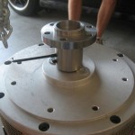
2 – Slide hub adapter onto motor shaft
There are two types of adapters that seem to be commonly used. The first is a taper-lock design, which I’ve previously written about. I ended up with a set screw/keyway and I think it will work fine. The inner diameter of the hub adapter was a few thousands smaller than the outer diameter of the driveshaft. Whether by design or just machining tolerances involved, it’s actually good in my book because once on it will be a tight fit, not relying only on the keyway to transmit the torque.
We didn’t want to force the hub on the shaft, because if it went on slightly off center it could bind up and not go further on or come off. Recalling some science class, we put the hub into the oven at 550 degrees for a while. I put it on some foil which worked out good because some machining oils came out and left a puddle in the foil. It also smoked a little and left a smell in the kitchen, so be sure to do this when your wife isn’t home.
After it was heated up, about 30 minutes, it slid right down the motor shaft. We placed two washers on the end of the motor to keep the hub adapter from rubbing. When measuring on Friday we made sure this would be ok and all it does it move the flywheel away from the adapter plate another 1/16″, which clears the bellhousing fine. Once cooled and snug, we removed them.
3 – Tighten the set screws
The set screws used a hex head so we added a drop of blue threadlocker and tightened them both down. I snugged them up and gave them a good tightness by hand.
4 – Place spacer ring onto motor end
This just slides into place, but does have to be right side up. Mine had a recess on the side that faced the adapter, which had a matching recess. A small ring fits in there and keeps them aligned around the center. Sliding a bolt or two through the holes will help align the ring with the holes in the motor. Once it is on the motor, it can be hard to rotate so it’s simpler to line it up right before dropping it down. It’s easy to remove and redo if it doesn’t go right on.
5 – Bolt adapter plate on ring
First thing to consider before you bolt the adapter plate on. Primarily, the orientation of the adapter plate determines how the motor will be installed in the car. The adapter plate will likely only bolt to the bellhousing one way. Make note of how the bellhousing and the adapter plate will align, and transfer that to the motor.
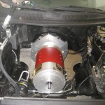
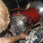
Think about where you want the motor terminals to be located and how that affects the rest of the motor. Something we missed was that the motor has a screen that has a bracket located opposite the motor terminals, sticking out about 0.5″. I had minimal clearance above the steering rack, so when we tried to install the motor it hit and wouldn’t go into the bellhousing.
We ended up placing the terminals so they point towards the driver’s side. I’d like to install the motor controller on top of the motor, just by the steering shaft so this will keep them on the same side. I did think about the steering shaft interfering with the terminals, but it will pass behind them.
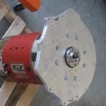
6 – Install flywheel
The flywheel installation is the same as it would be on a regular crankshaft, because that is what the hub adapter mimics. The only difference is that the hub adapter doesn’t have the locator pin, so the flywheel has to be rotated until all the bolt holes line up.
This is where we hit our first major problem. Two of the flywheel bolts wouldn’t go in until the flange was flush. After cranking on them a little bit, we decided to back them out and see what was wrong. The threads of the bolts were chewed up at the tips, so we looked in the holes and they weren’t threaded all the way through! Without any alternatives, we set out the Sears for a tap set.
Sears was pretty well cleared out of taps, except for the $200 75-piece deluxe set, including both metric and english. We realized we didn’t know what type we needed anyways, so neighbor Mike suggested we try Napa. Napa was able to look up the flywheel bolt information and supply us with a single tap that would suit our need, out the door for $24. Before heading home, we went ahead and stopped at Quizno’s for some subs since it was about 11:45. So a little over 2 hours in and we were about to start over.
In addition to chewing up the bolts, our previous flywheel attempt left some metal shreds down within the spacer ring. We needed to remove the adapter plate and spacer anyway to rethread the hub because that would also create some metal shreds we’d need to remove. The holes in the end of the motor lead directly into the motor housing, so we replaced the bolts a few turns in to prevent anything from dropping into the motor vitals. A little vacuum work and we were able to go back and repeat steps 4 – 6.
One problem is securing the flywheel and motor shaft while you tighten bolts. Since it isn’t mounted on an engine anymore, you don’t have the compression within the cylinders to help you resist turning. We screwed in two adjacent pressure plate bolts and used a metal bar between them to create a lever that would keep the motor from rotating.
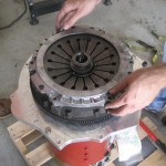
7 – Complete clutch installation
The remainder of the clutch install is no different than if it were going back on a gas engine. It’s a little bit easier if anything because gravity isn’t working against you when you are lining up the friction disc. We still used a clutch alignment tool though to keep things straight.
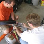
Installing the motor into the car
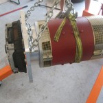
Once the adapter/clutch assembly is installed on the motor, it goes back on the transmission the same way the gas engine came out. We used a ratcheting strap wrapped several times around the center of the motor and two bolts through the adapter plate as our lifting points. It pays to adjust the chain and bolt placement until the motor is well balanced because that makes it easiest to manipulate into position.
Key points to think about prior to installation:
1. Recall that the adapter plate only connects to the transmission bellhousing one way, so it’s orientation determines how your motor will sit with regards to terminals pointing up, down, etc.
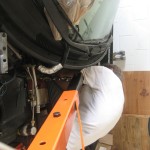
2. The motor will need to be as low as it will be in the engine bay while still being positioned 6-8 inches ahead of its final spot (away from the transmission). In our case, this meant that the steering rack was in the way before we could get the clutch and flywheel within the transmission.
3. Although the adapter plate was the best way to level and left the motor, in conjunction with the strap, we know that those bolts would need to be removed before it would mate flush with the bellhousing. If you do this, you’ll need to be able to set the motor down and release it from the engine hoist, at least undoing those bolts. We did this by placing a jack underneath the car and supporting the motor by it.
4. You’ll need to align the transmission input shaft with the pilot bushing inside the hub adapter. You normally won’t be able to see this, so once you get the clutch near the bellhousing, reach inside and feel how they align. We used a jack under both the motor and the bellhousing, as well as the straps on the motor to adjust everything until is lined up. Once it was close enough, we placed a long bolt through the adapter plate and bellhousing so we could let go and it would stay aligned. Two long screwdriver’s can also be used to help lift either the motor or the transmission.