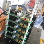
Got a lot done today, focusing on the rear of the car. The regulator octobox is cleaned up and I have the rest of the bolts and nuts needed for it. It is bolted to the car and ready for the regulators to be inserted.
The wooden battery cover was cut, routed and installed on hinges. I have a slight clearance issue with a battery post but I think I can work around that with shorter bolts on the hinge or rotating the battery if need be.
Last thing to do is route the AC from the gas cap to the charger and the DC from the charger to the battery pack Anderson connection. Once those are done the rear batteries can be reinstalled and wired up.
The front HV box will be ready to install after I mount the DC converter to its side. Then the Raptor can go back in followed by a cleanup of the LV wiring (vacuum pump primarily) and we’re ready for another road test.
I have an idea for the wooden cover. I’d like to stain it somewhat dark then have the Trans Amped logo printed across it, possibly with some stats on the car as well. I’ll probably focus on the logo to keep it clean.

This is the Trans Amped logo that my wife and brother had made for my birthday. The + and - are nicely incorporated into the traditional Firebird look.

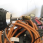
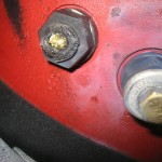
Drilling holes for the

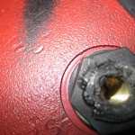
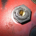
Mounted

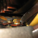
Wooden cover installed.

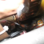
Conflict with hinge and battery post